
|
Breakneck Mountain Ntrak ModuleWiring |
| <-- Frame, Roadbed and Track | Scenery - Stage 1 --> |
It was recommended to put feeder wires every 2 feet, so I have a set of feeders at the 1, 3, 5, and 7 foot marks on my 8 feet of total length (adjusting slightly because of my curves and framework locations). This will help keep good electrical continuity across the module.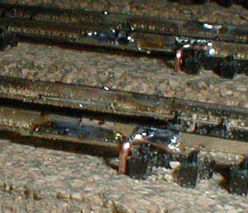 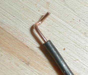 I have soldered some track sections and feeder wires to the rails. I have not filed the excess off the top of the rails yet. Notice the way the feeder wire is bent? (20ga. from Radio Shack) First I bent a little L on the end of the wire with needle-nose plyers, then I bent that L over, hopefully you can see what I mean from the photo! (knowledge courtesy of David D.) Feeder wire color: red on front rail, black on rear rail. The holes for the feeder wires were drilled directly next to the rail between ties using a 5/64" (1,98mm) bit. For your reference, the SAME location on the module (but from overhead) is used for the next 2 photos as the one above. 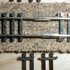 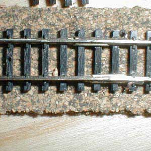 All track sections and feeder wires have been soldered and filed! Above is a Before and After. I took the extra ties and chopped off the "spikes" with an exacto, pushed them under the track and applied a drop of Krazy glue to each side. 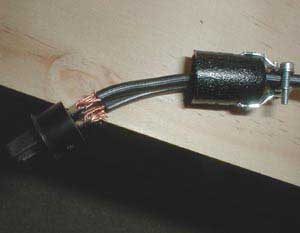 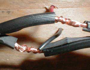 With some help from David D... A cinch jones (left) mechanical connection looks like this. I then soldered each, ribbed to wide pin, then wrapped each side with a small piece of electrical tape so power wouldn't try to jump between them and put the connector back together. A feeder wire (right) mechanical connection looks like this prior to soldering. As I used red feeders on the front rails, those were connected to the ribbed side of the bus wire. Notice how the feeder connections are staggered. This helps to prevent electrical shorts. I may wrap with electrical tape after soldering. Note: Rule of thumb: ribbed to wide, wide to front. This means connect the ribbed side of the 16ga zip cord to the wide pin of the cinch jones connectors. Also connect the feeders for the front rail to the ribbed side of the zip cord. 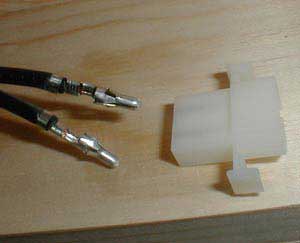 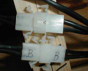 After cheating a bit at GATS (see below) by using wire nuts to join the bus wires together, I went to Radio Shack to pick up some connectors. Here you can see one of the bus wires with the male ends of the connector crimped (left). I finished soldering and labeling the wires and have inserted them into the plastic shells (right). Notice the little tab that clips them together, it must be released first before pulling the connectors apart.
Extra fun!All my hard work during the week paid off. GATS 2002 came to Raleigh, NC and my module was cleared to be placed on the end of a spur (turn-around loop to the right) on the layout! With trackwork complete and wiring in place, it was ready to be displayed as a "module under construction" at the show!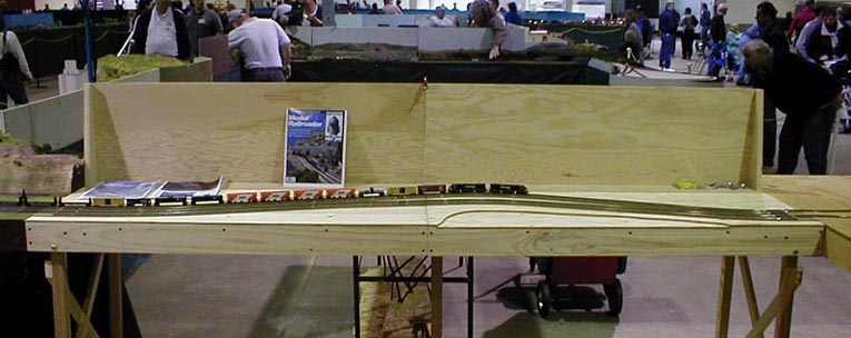 GATS - 4/6/2002 - Raleigh, NC. Entering the turn-around loop from the blue line. 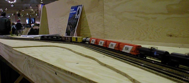 GATS - 4/6/2002 - Raleigh, NC. Exiting the turn-around loop on the red line.
|
